

Casa > Prodotti > Componenti > Interruttore automatico > Interruttore automatico monofase SF6 ad alta tensione da esterno 126KV HV

Interruttore automatico monofase SF6 ad alta tensione da esterno 126KV HV
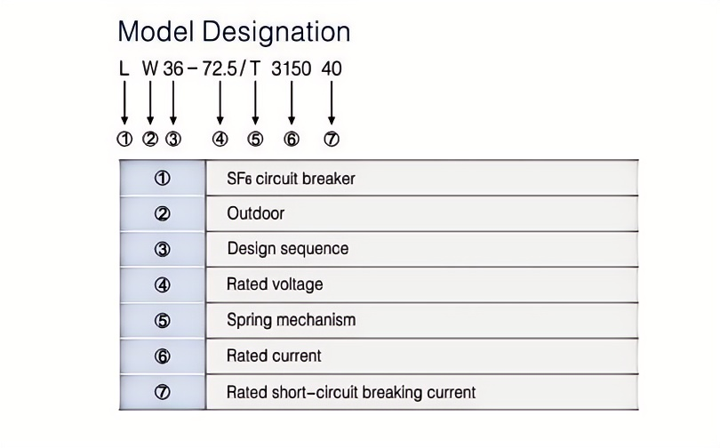
This 126KV HV Outdoor high-voltage SF6 single-phase circuit breaker is suitable for use in 72.5KV and 126KV three-phase AC 50HZ transmission and transformation systems. Its primary purpose is to regulate and safeguard these systems, but it can also function as a contact breaker and opener group, offering versatility in its applications.
Modello:LW36-126-4000A
Invia richiesta
Descrizione del prodotto
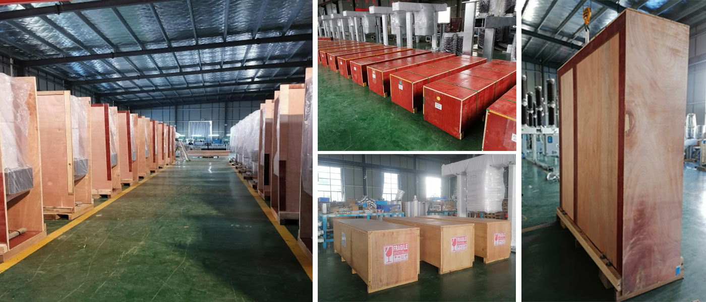
Installation Site

Workshop

Product show

package
Overview
This SF6 ceramic column single-phase circuit breaker is designed for outdoor use in 72.5KV and 126KV three-phase AC 50 systems. Its main purpose is to regulate and safeguard these systems, while also functioning as a contact breaker and opener group for added versatility. The LW36-126 Type circuit breaker operates on the principle of "thermal expansion + assistblowing" and is compatible with a CTB-1 spring operating mechanism only. It adheres to the standards outlined in GB1984-2003 for "AC High Voltage Circuit Breaker" and meets the criteria set by the International Electrotechnical Commission standard IEC62271-100:2001 for "High Voltage Switchgear and Control Equipment Part 100: High Voltage AC Circuit Breaker".
The main features of the circuit breaker:
This circuit breaker utilizes a self-sustaining arc quenching method, boasting exceptional interrupting capabilities, rapid arc extinction, extended lifespan, and minimal operating noise. The device employs SF6 gas, renowned for its superior insulating and arc quenching properties, as the dielectric medium. This eliminates the risk of fires and explosions, making it suitable for deployment in densely populated regions. The breaker features a spring-actuated operating mechanism, distinguished by its simplicity, compact design, and unwavering safety and reliability.
Environmental conditions
Ambient temperature -30'C*+40'C(special requirements -40 'C*+40C)
Above sea level <4500m
Air humidity:
Relative temperature: daily average is not more than 95%
The monthly average is no more than 90% (25 C)
Saturated vapor pressure: daily average is not more than 2.2X 10 MPa
The monthly average is not more than 1.8X 10 MPa
Wind pressure is not more than 700P
Wind pressure is not more than 700P
Ice thickness 10mm
Earthquake intensity: Horizontal acceleration: <0.3g, Vertical acceleration: <0.15g
Irradiance: 0.1W/cm3(At a wind speed of 0.5 m/s)
Maximum daily temperature difference:25 ℃
Nominal creepage distance: 31mm/kV
No flammable explosion hazard, chemical corrosion, severe vibration
Main technical parameters
Main technical parameters of the circuit breaker :

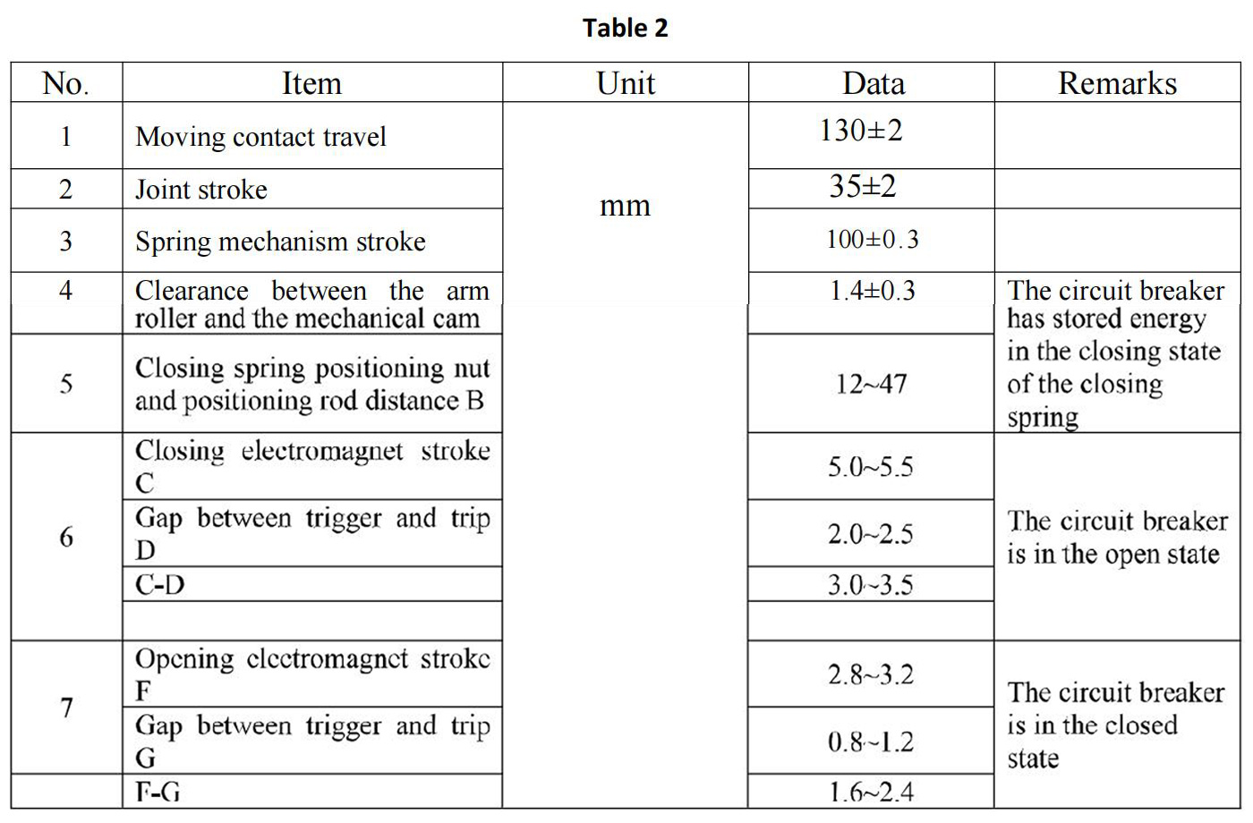
Mechanical parameters of circuit breaker and operating mechanism
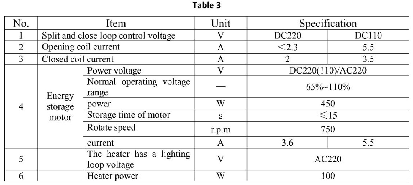
Control loop and auxiliary loop parameters
SF6 Gas pressure parameter

Product structure and principle
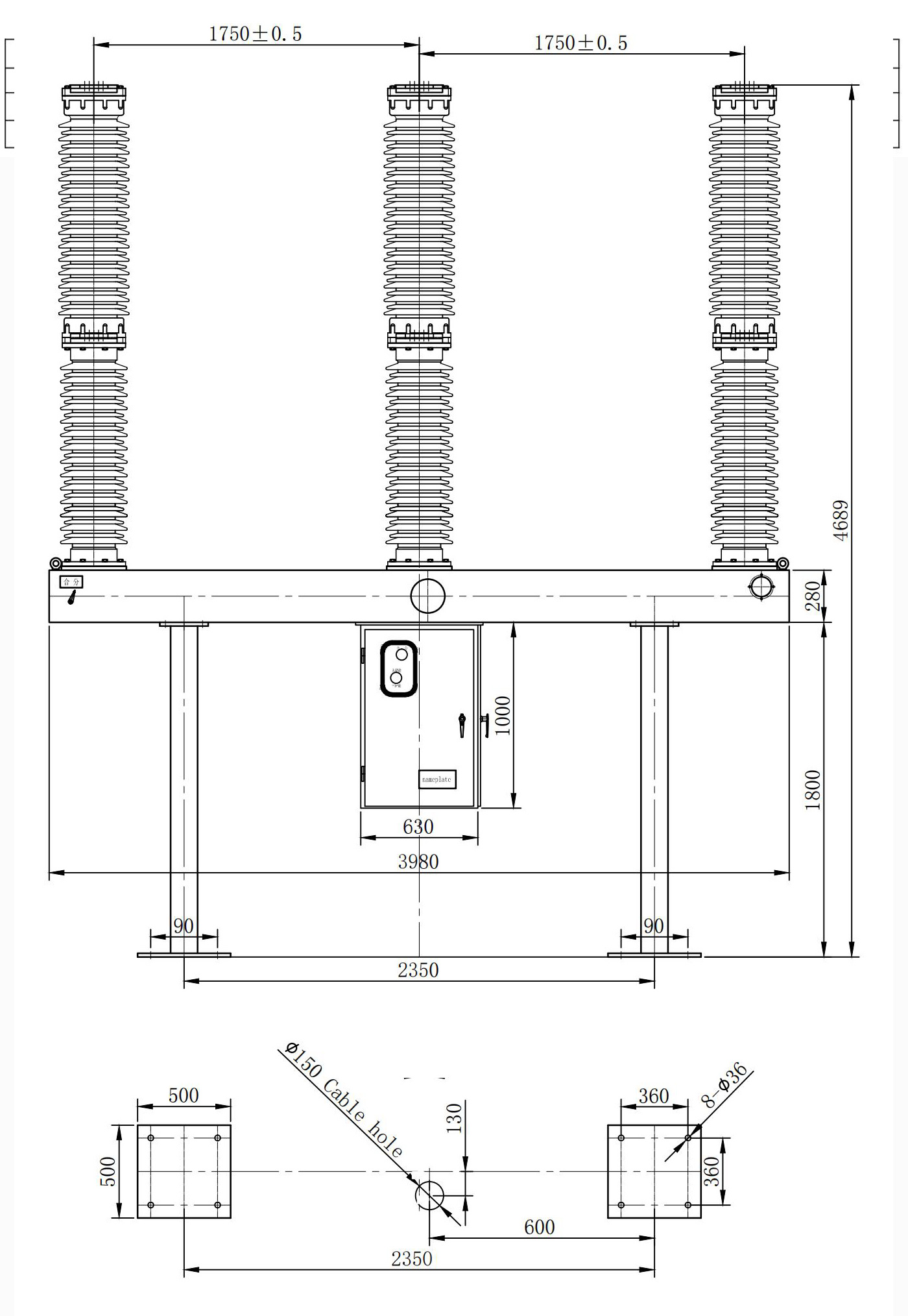
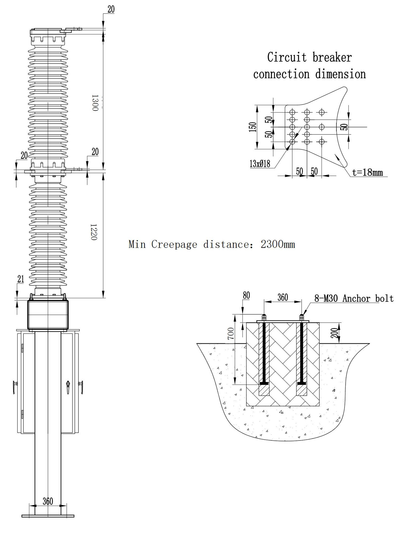
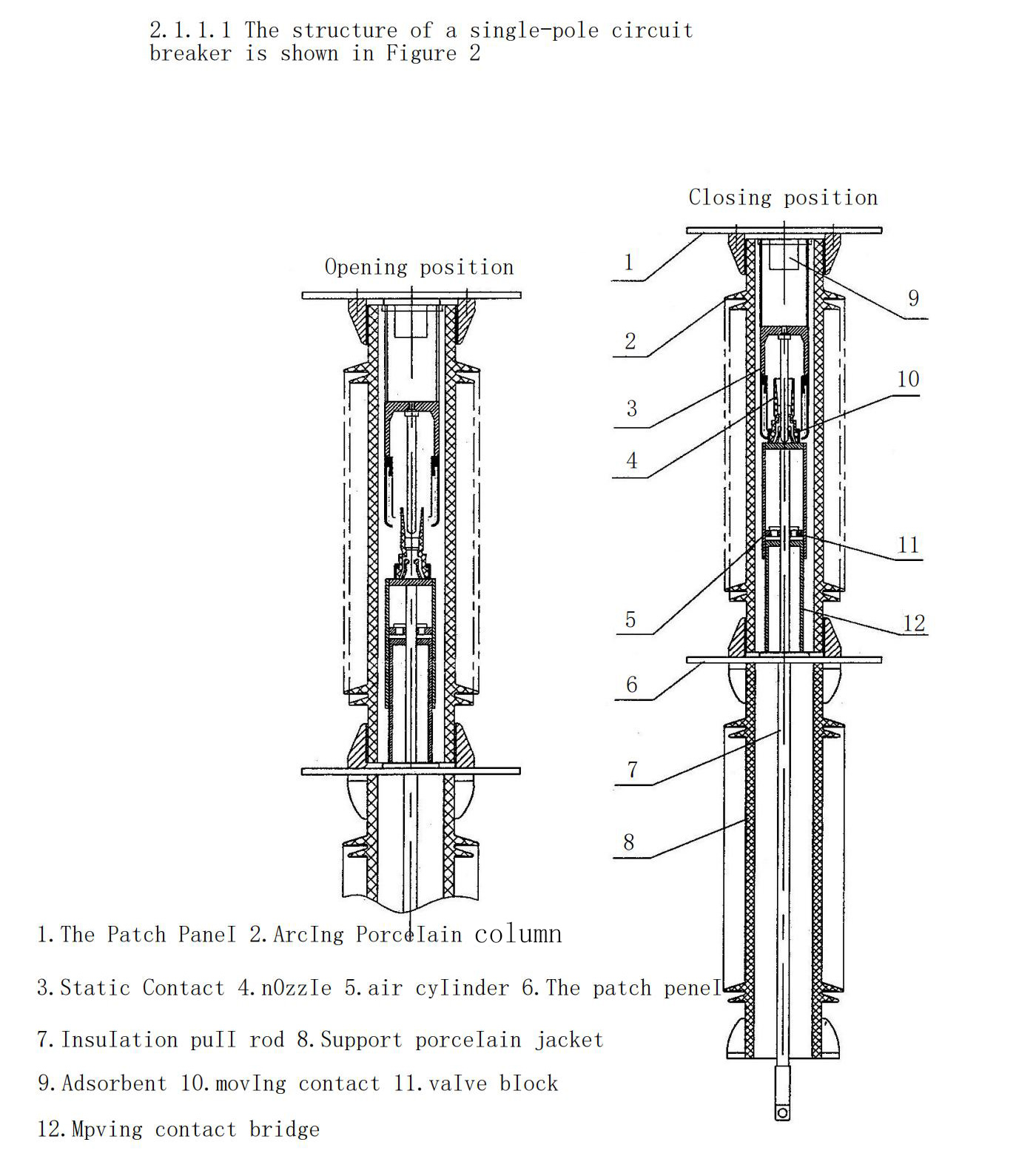
The product's overall design incorporates a self-energy arc extinguishing chamber, with each individual pole referred to as a pole. Each circuit breaker consists of three poles, which are mounted on a single frame and operated by a spring mechanism with mechanical linkages between the poles. The product's upper portionishing porcelain sleeve, while the middle section consists of the pillar porcelain sleeve, the frame, and the mechanism box. The lower part of the frame houses the mechanism box, which contains a spring operating mechanism and an electric control part. The mechanism's output pull rod is connected to the B arm. The SF6 gas density controller is mounted on the front of the frame, with the frame supported by struts. The control principle is divided into two schemes: single trip gate and double trip gate. The electrical control schematic diagram and secondary wiring diagram are based engineering technology agreement shall shall be provided at random.
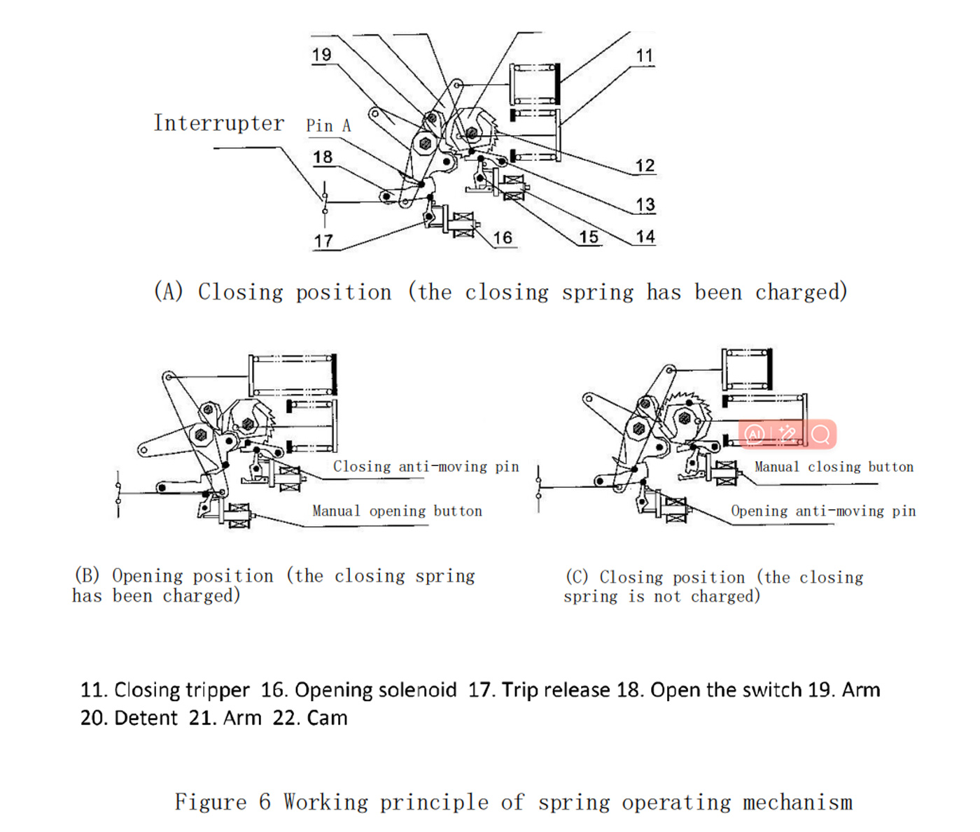
Working principle of spring operating mechanism
The opening operation is show on n in Figure 6-(A).
The spring mechanism is in the closing position and the opening spring 10 and the closing spring 11 have been stored. The arm 19 and 21 are subjected to a counterclockwise moment of the trip spring 10, which is blocked by the trip holding pawl 18 and the trip release 17.
The opening operation steps are as follows:
a. After the opening coil 16 receives the opening signal, the iron core acts to strike the opening release 17;
b. The opening release 17 rotates clockwise, releasing the opening to hold the dice 18;
c. Opening the dice 18 clockwise rotation, release pin A;
d. The arm 19 and 20 are rotated by the thrust of the trip spring 10 in a counterclockwise direction;
e. The arm 21 passes through the connecting rod 8 of FIG. 4 and other transmission elements connected thereto, so that the arc-moving chamber moving and static contacts are quickly separated, and the circuit breaker is opened.
Closing operation is shown in Figure 6-(B).
The spring mechanism is in the opening position, the closing spring 11 has stored energy, and the ratchet bearing is subjected to a counterclockwise moment of the closing spring 11 connected to the ratchet wheel 12, and the torque is closed by the closing holding latch 13 and the closing release 15.
The closing operation steps are as follows:
a. After the closing coil 14 receives the opening signal, the iron core acts to strike the closing release 15;
b.Closing trip unit 15 rotates clockwise,releasing the closing and holding the dice 13;
c. Closing keeps the dice 13 rotating counterclockwise, releasing the pin B;
d. The ratchet 12 rotates counterclockwise under the action of the closing spring 11, and simultaneously drives the ratchet shaft to rotate, so that the cam 22 pushes the arm 19 to rotate clockwise, and drives the arm 21 on the arm shaft to rotate clockwise. The compression opening spring 10 stores energy;
e. The arm 21 is quickly closed by the connecting rod 8 of Fig. 4 and other transmission elements connected thereto.
f. The state of the mechanism after the closing operation is completed is shown in Figure 6-(C), and the A pin is again locked to keep the latch 18 locked.
Spring-loaded spring energy storage
Once the mechanism has finished closing, the closing spring is released, and the pawl shaft is engaged with the motor via the gear. The motor then starts to energize the closing spring, ready to perform the next closing operation.
The energy storage action of the closing spring is as follows:
a. The motor is started to rotate the pawl shaft;
b. The two pawls 20 on the eccentric pawl shaft alternately mesh with the teeth on the ratchet 12 in the transmission of the pawl shaft to rotate the ratchet;
c. The ratchet 12 rotates counterclockwise to drive the pull rod to store the closing spring 11;
d. After passing the dead point, the ratchet shaft is given a counterclockwise rotational moment by the closing spring 11l, and this torque is locked by the pin B being closed by the pin B.
e. Figure 6-(A) shows the state of the mechanism after the closing spring is stored.
Reclosing operation
Since the closing spring has stored energy when the circuit breaker is in the closing position, the circuit breaker can be operated with the 0-03S-CO reclosing operation.
Principle
a. Valves VA, VB, VC, VD should be in the open position under normal conditions to maintain consistent SF6 gas pressure in three-phase circuit breakers and densitometers.
b. The air supply port valve VF (or self-locking connector) should be in the closed position under normal circumstances. When the density of SF6 gas decreases and an alarm is issued,SF6 gas can be supplied by the air supply port,and it can be replenished by the air supply port under the live operation condition.
c. The SF6 gas density controller is a temperature-compensated electrical component. The rated pressure of SF6 gas at 20 C, the alarm pressure, and the blocking pressure are shown in Table 4. The SF6 gas temperature-force curve is shown in Figure 10. Now the pressure gauge is usually used. Density controller two-in-one density meter, do not need to consider the SF6 gas temperature -the characteristics of the force curve.
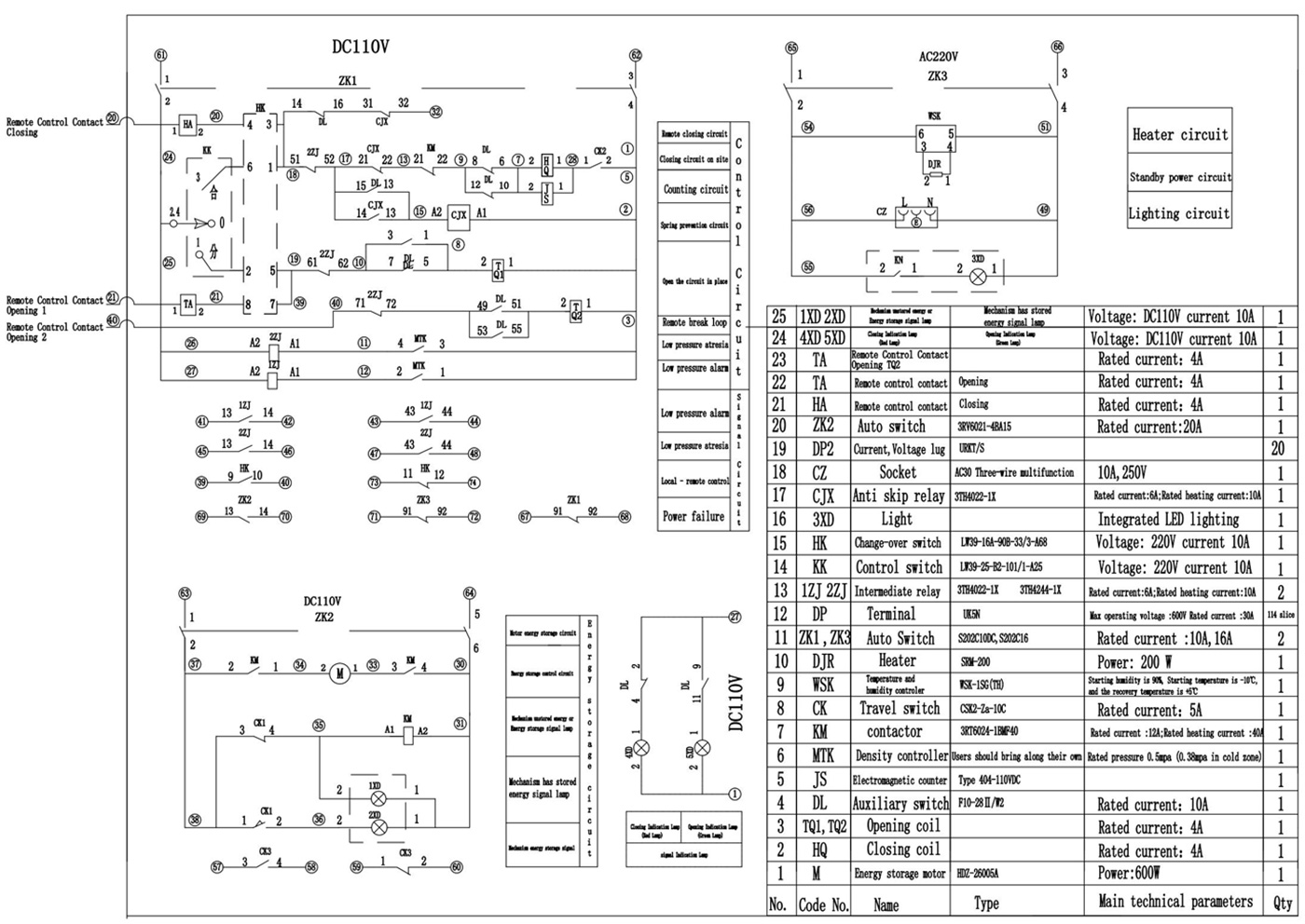
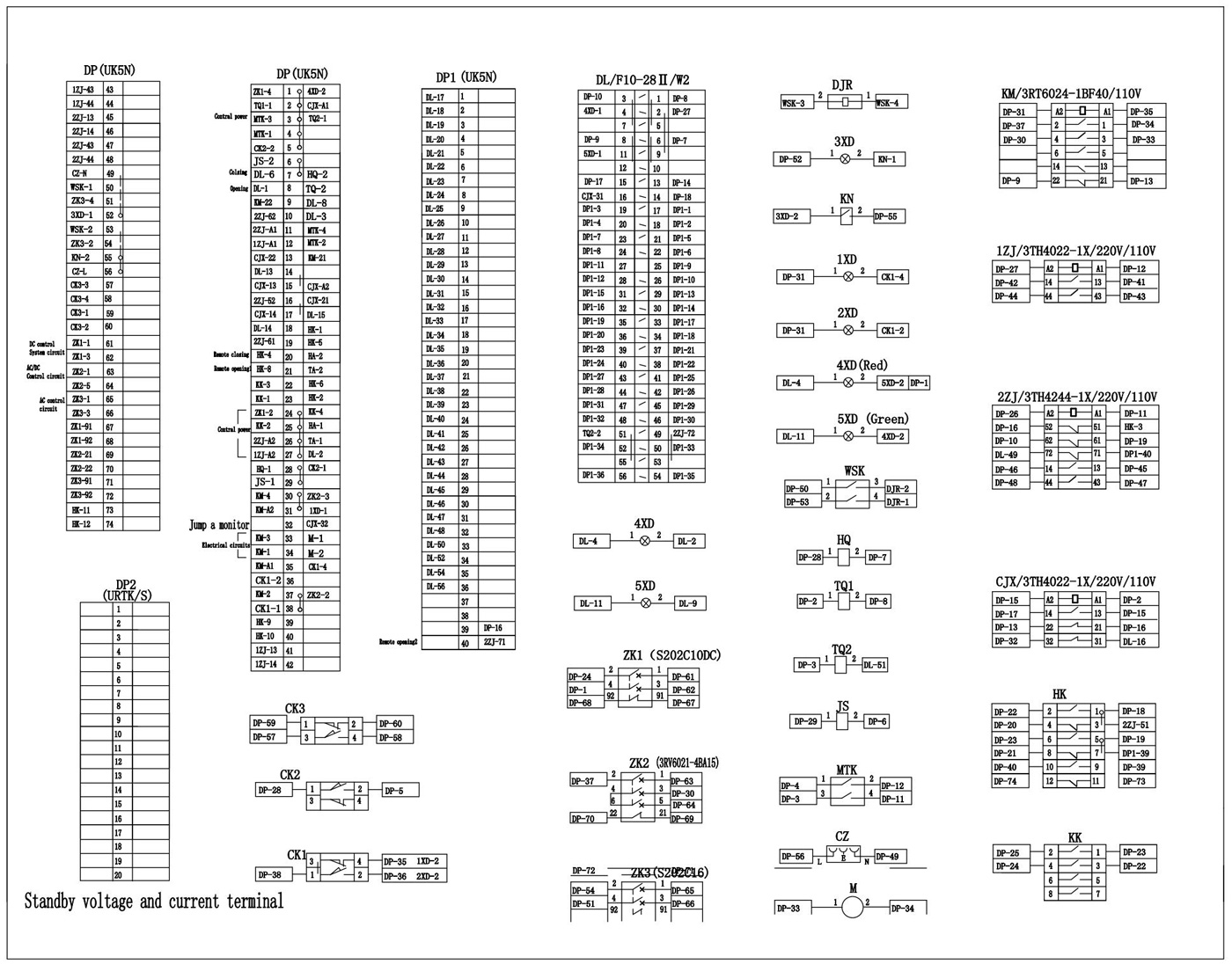
Control system
Within the electrical control system, situated at the organizational level, are various key components, including operating switches, automatic switches, trip switches, relays, terminals, closing coils, motors, ShiKong devices, and heaters. These essential elements enable a range of functions, such as control of switching and braking, prevention of jumping, energy storage through closing springs, motor control and protection, SF6 gas pressure monitoring, as well as heating and lighting capabilities.
Control Principles and Wiring References Annex IIl: Electrical Control Schematic and Annex IV: Secondary Wiring Diagram
Acceptance, opening and storage
Upon receiving the circuit breaker at its destination, the user should inspect the goods to ensure they match the packing list and then submit an acceptance report. If any damages, discrepancies in quantity, or other issues are noted, please reach out to our company.
Handling breakers and unpacking precautions are as follows:
a. All parts of the circuit breaker should be protected against moisture during loading and unloading.
b. Avoid violent impact when handling the circuit breaker.
c. Do not open any valves of the circuit breaker.
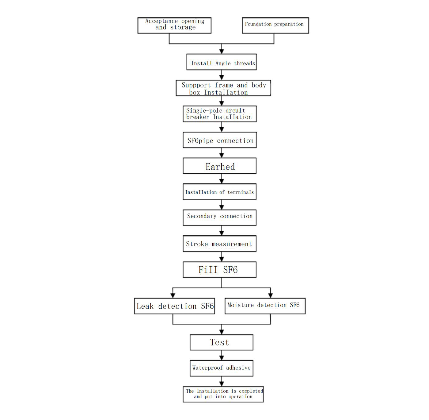
Installation and commissioning
Field installation flow chart
Instructions for ordering
When ordering the circuit breaker, the following should be noted
a. Type and mechanism type of circuit breaker
b. rated electrical parameters (voltage and current);
c. uses environmental conditions;
d. operation power type
e. primary terminal wiring direction;
f. spare parts, special tools, specialties, etc.name and quantity of equipment.
Tag caldi: Interruttore automatico in vuoto media tensione per esterni, VCB alta tensione per uso esterno, Interruttore automatico per esterni media tensione, Interruttore automatico in vuoto HV per applicazioni esterne, VCB alta tensione per esterni, VCB esterno media tensione, Interruttore automatico per esterni alta tensione, VCB MV per esterni, Media tensione interruttore automatico per vuoto esterno, VCB esterno ad alta tensione
Categoria correlata
Invia richiesta
Non esitate a dare la vostra richiesta nel modulo sottostante. Ti risponderemo entro 24 ore.
prodotti correlati